
Now Playing VFD
-DPOKpU3V.jpg)
Backstory
Sometime in 2021 I was browsing eBay for vintage and unique displays as I am want to do, and came across a very cool 40x2 character display based on the recently forgotten Vacuum Fluorescent Display technology. Most readers likely are familiar with this technology existing in the majority of cash registers from the late 80s to the early 2000s as well as Boom Box displays and head units for car stereos.
VFDs use a fluorescent anode that gets excited by a cathode grid, not all that different from how old tube TVs work, but with lower voltage and a multiplexed grid in close proximity to the phosphor anodes instead of an electron tube.
I found this particular display (a Futaba M402SD10FJ) by looking for displays that had a serial interface so I could get up and running quickly, but after it arrived and I looked up the datasheet I realized the serial interface was not like any I had interfaced with in my limited (at the time) experience. I flipped the resistor on the board that would switch it from parallel mode to serial mode and hooked it up to an arduino dev board I had and tried to pipe some ASCII commands to it, but had no luck. I futzed around with it for a few days and eventually put it in my bin labeled "displays" and forgot about it for a year and a half.
Eventually I got to the bottom of my project list and pulled the display out again. By this point I had been working with archaic serial protocols from bygone eras quite a bit at my job and was feeling more confident. I found a more complete version of the manual and went to work. After some time I decided to look at the parallel interface more, as that is what it seemed like the majority of VFD's used and I found a few examples on the net but none that matched this control board. After looking at it more, I realized that the 16x2 displays I used as a teen just getting in to microcontrollers (before the i2c and serial driver boards became the norm) had a similar pin count to this parallel interface. I started doing some googling for "Motorolla M68" as described in the datasheet but could not find much.
Eventually I found a forum thread (that I can no longer find) alluding to a Motorolla parallel interface for character displays and one of the replies alluding to the fact that the famous Hitachi HD44780 was built to be compatible with the M68 series displays that were prevalent in the 1980's. This Hitachi driver has been cloned dozens of times and is the driver board supported by the Arduino official LCD library, which is why I had used it all those years ago.
I still had some issues getting it to work, but I noticed comment on a similary eBay listing that indicated the user had one of these displays working with an arduino, I noticed the user's username was in a format that looked a lot like a ham radio callsign, found him on QRZ.com (a sort of social media for us radio amateurs) and shot him an email. It turned out he was indeed the commentor on eBay and he provided some much needed guidance (I had two pins swapped due to misreading the silkscreen on the display) and he set me on my way.
The Build
Now that we have the boring backstory out of the way, here is the nitty gritty on how I got this working.
Spotify
After I got the display working with an arduino, I had to figure out what I wanted to use it for. I had recently build a gaming PC and wanted to know what song I was listening to on the streaming service Spotify while gaming and without tabing over to the Spotify app.
I looked into their API, and it seemed like kind of a pain to deal with the auth and everything so I kept looking for an easier method. Eventually I found that there was a pretty good official Home Assistant integration. Being an avid Home Assistant user, I followed the guide and got that working.
Essentially this integration requires that you get a Spotify dev key (free and easy to obtain at the time of this writing) and it allows the user to control playback as well as get information about the media playing on a users account. One key benefit here is that the integration handles all of the auth and polling rate limiting, and also provides information regardless of where the media is playing as it is tied to the users account. This meant that I could be listening through a standalone streaming device or my PC and I would still get that data. It also meant I did not need to constantly run a background app on my PC to scrape that data from the Windows Media Control Center.
The Electronics
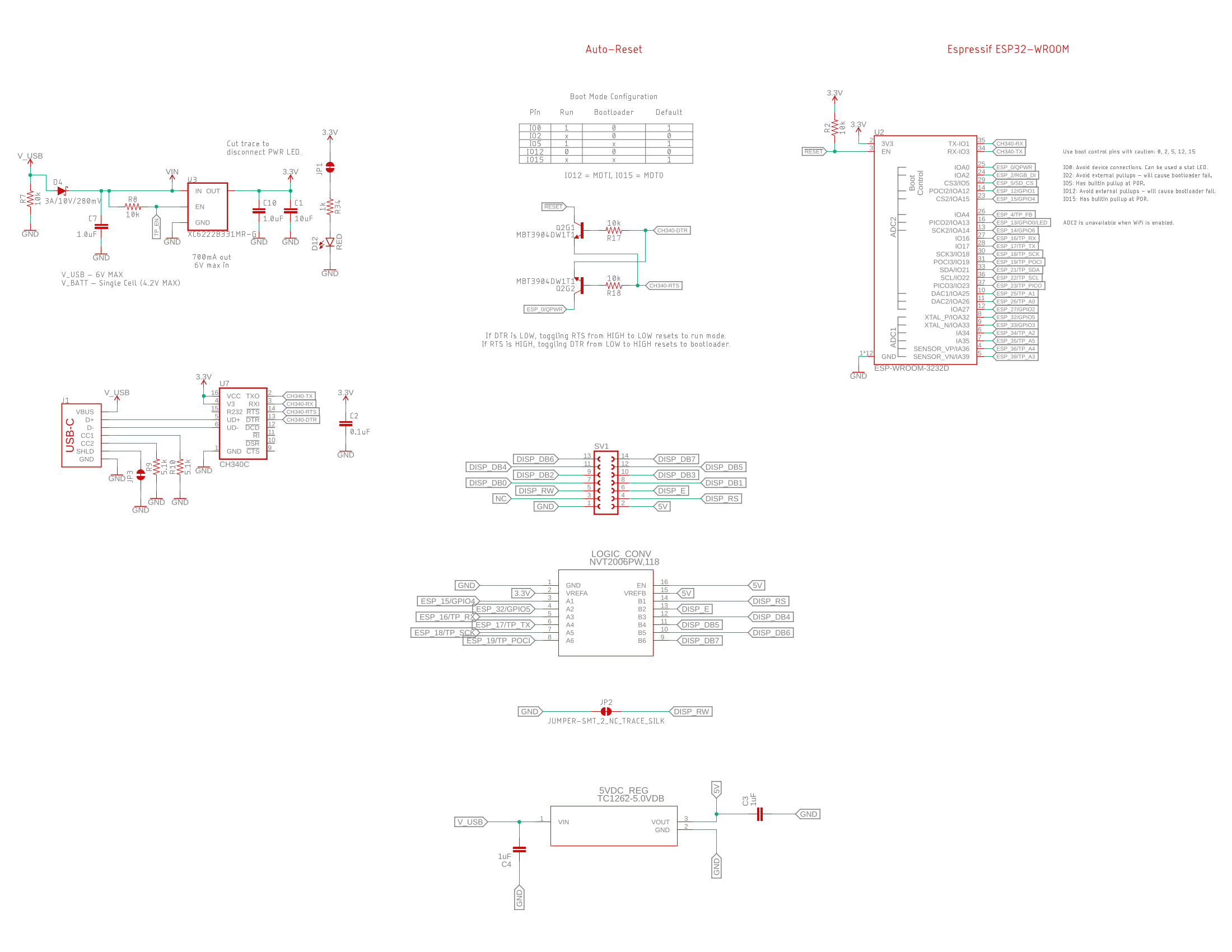
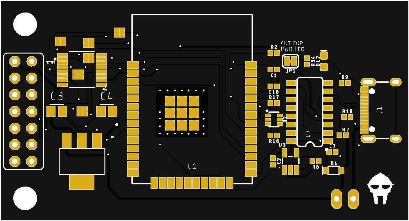
Since the display was going to need network access, the choice of micro controller was pretty obvious. I grabbed one of my ESP32's off the shelf and hooked up some jumpers. It required a logic level converter as well since the ESP32 was 3.3v and the arduino I was originally testing with, and the display itself, were 5v. I got that working and decided I wanted to make it a bit neater so I fired up EagleCAD.
Not my greatest work, but it is functional. I accidentally used 0402 components which was a real pain to solder. I also used an ESP32 module that did not support USB (I do not remember if the S3's and C2's were out at the time) so I had to include my own USB/Serial chip. Also the USB-C port I used was single sided and included all of the pins so that was also a bit of a pain.
The PCB is pretty simple, just a logic level converter, power supply, ESP32, USB-C port, and a header that matches the header on the display driver board. The regulator did require a bit of work to find, needed to be an LDO as the display does not work very far below 5vdc.
Software
The ESP32 is running ESPHome which is an offshoot of the Home Assistant project. ESPHome makes it convenient to write quick YAML files that update via OTA through the ESPHome docker container. All the plumbing is there so I only needed to write the logic to convert the incoming Unicode text from the Spotify integration to the character map that the display can support and some logic to scroll the text across the display if it was wider than 40 characters. There is a unix bar separator between the end of the line and the begining so the user knows when the scroll has wrapped around again. The text will remain static unless the text is greater than 40 characters including spaces and punctuation.
ESPHome supports the majority of Arduino standard libraries out of the box, so using the LCD library was as simple as including platform: lcd_gpio in the config and providing the appropriate pins.
Please note that this code is a few years old and not as clean as I would like but I cannot be bothered to fix it at the moment.
I also need to go back at some point to add better parsing of characters outside of the character set. I listen to a fair amount of music in non english languages so it would be nice to have some sort of romanization lookup or something. TBD.
The YAML requires some stuff to set up the device:
esphome:
  name: vfdisplay

substitutions:
  lcd_width: '40'
  lcd_height: '2'

esp32:
  board: esp32dev
  framework:
    type: arduino

globals:
  - id: api_has_values
    type: bool
    initial_value: 'false'

# Enable logging
logger:
  level: VERY_VERBOSE
  baud_rate: 9600
  logs:
    api: VERY_VERBOSE
    homeassistant: VERY_VERBOSE
    api.service: VERY_VERBOSE

# Enable Home Assistant API
api:
  encryption:
    key: ""

ota:
  password: ""

wifi:
  ssid: !secret wifi_ssid
  password: !secret wifi_password

  manual_ip:
    # Set this to the IP of the ESP
    static_ip: 192.168.1.67
    # Set this to the IP address of the router. Often ends with .1
    gateway: 192.168.1.1
    # The subnet of the network. 255.255.255.0 works for most home networks.
    subnet: 255.255.255.0

  # Enable fallback hotspot (captive portal) in case wifi connection fails
  ap:
    ssid: "Vfdisplay Fallback Hotspot"
    password: "KpLsLp8MOhqt"

text_sensor:
  - platform: homeassistant
    id: playing_artist
    entity_id: sensor.artist_name
    internal: true

  - platform: homeassistant
    id: playing_song
    entity_id: sensor.song_name
    internal: true
    on_value:
      then:
        - globals.set:
            id: api_has_values
            value: 'true'
Then there is the actual display configuration which is in the same yaml file. I have separated out the C code contained within the lambda within for ease of reading
display:
  - platform: lcd_gpio
    dimensions: 40x2
    data_pins:
      - GPIO16
      - GPIO17
      - GPIO18
      - GPIO19
    enable_pin: GPIO32
    rs_pin: GPIO15
    lambda: |-
      if (strncmp((id(playing_song).state.c_str()), "unknown", 7) != 0)
      {
        std::string str1 = id(playing_song).state.c_str();
        std::string str2 = id(playing_artist).state.c_str();

        std::string unicode_apostrophe = "’";
        std::string ascii_apostrophe = "'";
        size_t start_pos = 0;
        while((start_pos = str1.find(unicode_apostrophe, start_pos)) != std::string::npos) {
            str1.replace(start_pos, unicode_apostrophe.length(), ascii_apostrophe);
            start_pos += ascii_apostrophe.length();
        }
        size_t start_pos1 = 0;
        while((start_pos1 = str2.find(unicode_apostrophe, start_pos1)) != std::string::npos) {
            str2.replace(start_pos1, unicode_apostrophe.length(), ascii_apostrophe);
            start_pos1 += ascii_apostrophe.length();
        }


        static int p1 = 0;
        static int p2 = 0;

        // If the string fits within the $lcd_width, return it as is
        if (str1.size() <= $lcd_width) {
            it.printf(0, 0, "%s", str1.c_str());
        }
        else
        {

            // Create a new string with the input string added at the end for continuous scrolling
            std::string modifiedInput = str1 + "   |   " + str1;

            // Get the substring starting from the current p1
            std::string output = modifiedInput.substr(p1, $lcd_width);

            // Increment the p1 for the next call
            p1++;

            // If we've reached or passed the end of the original string (not including the added part), loop back to the beginning
            if (p1 >= (str1.size() + 7)) {
                p1 = 0;
            }

            it.printf(0, 0, "%s", output.c_str());
        }

        if (str2.size() <= $lcd_width) {
            it.printf(0, 1, "%s", str2.c_str());
        }
        else
        {

            // Create a new string with the input string added at the end for continuous scrolling
            std::string p2modifiedInput = str2 + "   |   " + str2;

            // Get the substring starting from the current p1
            std::string p2output = p2modifiedInput.substr(p2, $lcd_width);

            // Increment the p1 for the next call
            p2++;

            // If we've reached or passed the end of the original string (not including the added part), loop back to the beginning
            if (p2 >= (str2.size() + 7)) {
                p2 = 0;
            }

            it.printf(0, 1, "%s", p2output.c_str());
        }
}if (strncmp((id(playing_song).state.c_str()), "unknown", 7) != 0)
{
std::string str1 = id(playing_song).state.c_str();
std::string str2 = id(playing_artist).state.c_str();
std::string unicode_apostrophe = "’";
std::string ascii_apostrophe = "'";
size_t start_pos = 0;
while((start_pos = str1.find(unicode_apostrophe, start_pos)) != std::string::npos) {
str1.replace(start_pos, unicode_apostrophe.length(), ascii_apostrophe);
start_pos += ascii_apostrophe.length();
}
size_t start_pos1 = 0;
while((start_pos1 = str2.find(unicode_apostrophe, start_pos1)) != std::string::npos) {
str2.replace(start_pos1, unicode_apostrophe.length(), ascii_apostrophe);
start_pos1 += ascii_apostrophe.length();
}
static int p1 = 0;
static int p2 = 0;
// If the string fits within the $lcd_width, return it as is
if (str1.size() <= $lcd_width) {
it.printf(0, 0, "%s", str1.c_str());
}
else
{
// Create a new string with the input string added at the end for continuous scrolling
std::string modifiedInput = str1 + " | " + str1;
// Get the substring starting from the current p1
std::string output = modifiedInput.substr(p1, $lcd_width);
// Increment the p1 for the next call
p1++;
// If we've reached or passed the end of the original string (not including the added part), loop back to the beginning
if (p1 >= (str1.size() + 7)) {
p1 = 0;
}
it.printf(0, 0, "%s", output.c_str());
}
if (str2.size() <= $lcd_width) {
it.printf(0, 1, "%s", str2.c_str());
}
else
{
// Create a new string with the input string added at the end for continuous scrolling
std::string p2modifiedInput = str2 + " | " + str2;
// Get the substring starting from the current p1
std::string p2output = p2modifiedInput.substr(p2, $lcd_width);
// Increment the p1 for the next call
p2++;
// If we've reached or passed the end of the original string (not including the added part), loop back to the beginning
if (p2 >= (str2.size() + 7)) {
p2 = 0;
}
it.printf(0, 1, "%s", p2output.c_str());
}
}Enclosure
The enclosure is a pretty simple 3d Printed box I designed with a laser cut front panel that I cut out of smoked transparent acrylic. This cuts down on the intensity of the display a bit and is similar to what you would have seen in old cash registers. The smoke tint is enough to make the actual display and pcb all but invisible so the letters appear to hang in the void.
I added two little tabs that I sized for my computer monitor so that the front lip of the display aligns with the front of the monitor.
There is a small slit in the back that allows for a USB-C cable to pass in. If I were to do this again I would use a right angle PCB mounted connector so the cable could plug directly into the back of the enclosure and the enclosure itself could be thinner.
I also added a small switch on the side, if I were to do this again I would have added a mosfet or some other method of cutting of power to the display to reduce wear when idle. As it currently stands I have to manully switch it off if I am not using it for an extended period of time. I routinely forget this.
VFDs should have pretty long run time but it that will be extended by turning off the warming current for the filaments.
Below is the fully assembled enclosure with screws and all. I need to do a bit of clean up and I will post the model itself.
Conclusion
Overall this was a very satisfying project to complete and I have used it every single day since I built it two years ago. It works exactly as I envisioned and looks very nice. The vintage display aesthetic is just what I was looking for.
In the future I would like to make the modifications I have mentioned above and post the files to aid anyone else trying something similar, however these displays are becoming quite difficult to source. There appears to be a few companies selling them that claim that they are new stock (i.e. currently in production) for over $100 but I find that very hard to believe and they are likely new old stock.
-ECkf-O2S.jpg)
Copyright
Copyright Ownership:prairielandelec
License under:Attribution-NonCommercial-NoDerivatives 4.0 International (CC-BY-NC-ND-4.0)